Introduction to Bolt WiFi Module
The Bolt IoT Platform consists of three major components:
- Bolt WiFi module
- Bolt Cloud
- Bolt Mobile App
In this article, I will share with you the specifications of the WiFi Modules and how to use them.
Here are the photos of the WiFi module:
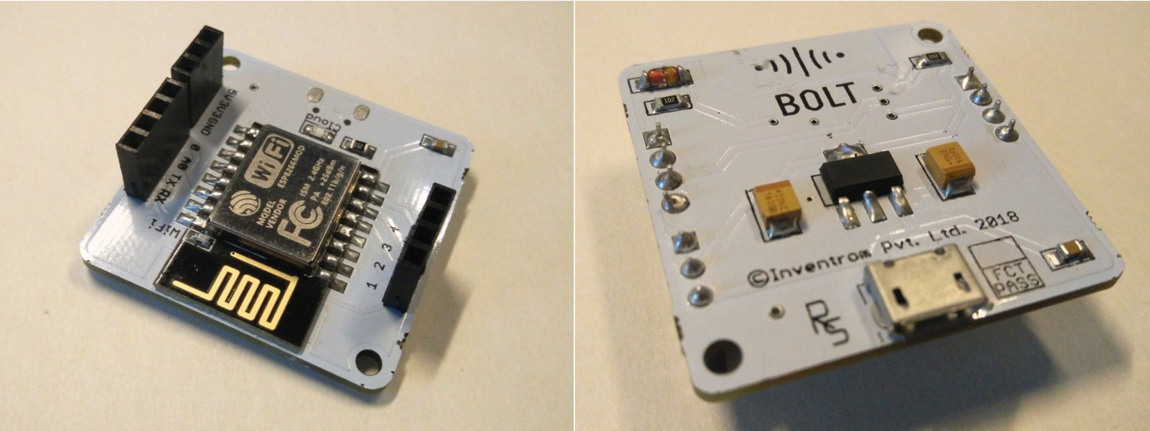
Bolt WiFi Module. Front and backside.
Bolt WiFi Module Pinouts
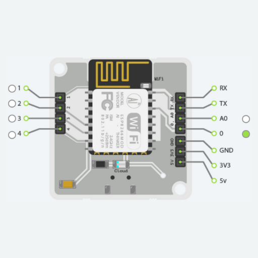
WiFi Module Pinouts
| Pin | Type | Description |
| A0 | Analog Input | This pin comes with an ADC (Analouge to Digital Converter). This is the only pin to which we can connect an Analouge sensor. This is an input only pin i.e. it can only collect input. It does not give any output. |
| 0 , 1, 2, 3, 4 | Digital I/O (Input and Output) | You can only connect a digital sensor to this pin. |
| TX | UART Pin | |
| RX | UART Pin | |
| 3.3V | Power pin which gives a value of 3.3 volts. | |
| 5V | Power pin which gives a value of 5 volts. | |
| GND | Ground pin | Used to ground and complete any circuit connection. |
When you design any circuit, choose the correct pin based on your requirement. Here are few examples:
- If you are connecting an LDR (Light Dependent Resistor) then use the pin A0. This is because LDR is an analogue sensor and A0 is the only pin with an ADC on it.
- If you are connecting an LED then use any pin from 0 to 4. All these five pins are Digital I/O (Input and Output) pins. Since LED is an output device you may connect to any of these pins. Keep in mind that you cannot connect it to Pin A0 as it is an analog only pin.
