Light Monitoring for Plants using LDR (Light dependent resistor)

Things used in this project
Hardware components
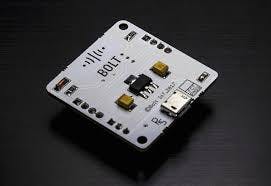
- Bolt IoT Bolt WiFi Module
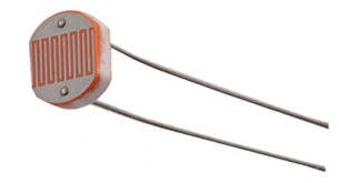
- LDR (Light Dependent Resistor)
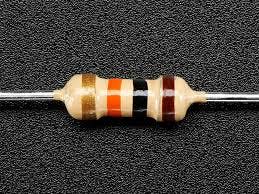
- Resistor 10k ohm
- Jumper wires
Software apps and online services
- Bolt Cloud
- Bolt IoT Android App or Bolt IoT iOS App
Story
We all know that plants require sunlight for their healthy growth. However, at times we may not be able to keep a track of it or maybe we are not sure if our plants are getting enough sunlight.
In this project, we will build a system so that we could monitor the light our plants get and send the data to Bolt Cloud. In fact, this product is commercially available by Xiaomi . But as makers, we shall build this product on our own.
What will you build as part of this project?
- Using this project, you will be able to build a light monitoring system to collect the data and send it to the cloud.
- You will also learn to visualise the data in form of graphs.
- This project can then be extended to Predict the future sensor values via machine learning over the Bolt Cloud.
- You may also send alerts over SMS and email using the features of Bolt Cloud Pro.
Gathering all required components
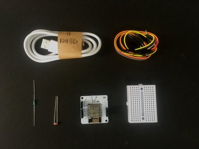
These are the components required.
- Bolt WiFi Module
- LDR (Light Dependent Resistor)
- Resistor 10K
Let's get started and build our system
Before you move to Step 1, make sure that your Bolt WiFi Module is connected to Bolt Cloud and the green LED on Bolt Module is Glowing. If not then follow the steps in this project to set up the device: Setting Up the Bolt WiFi Module
Part A: Building the circuit
Switch off before you get started
Make sure you have not powered on your Bolt Module while connecting the circuit. This will ensure that in case we make any mistake, it will not short circuit your device. Switch off the power if it is connected.
We need to do two steps to build our circuit:
Step 1: Connect one end of the LDR to the A0 (analog) pin of the Bolt device and other ends of the LDR to the 5V pin of the Bolt as shown in the image below.
Step 2: Connect the 10K ohm resistor between the GND and A0 pin of the Bolt so that LDR and the resistor form a series connection.
Confused about the two steps above? Don't worry. I will explain the above two steps in detail with help of images. Connect your circuit as shown in the images.
Before you connect, if you do not have experience with breadboard then I recommend watching this video: How to Use a Breadboard.
Step 1: Here are all the components that you will require
Step 2: Connect the LDR to the breadboard in the holes as shown below
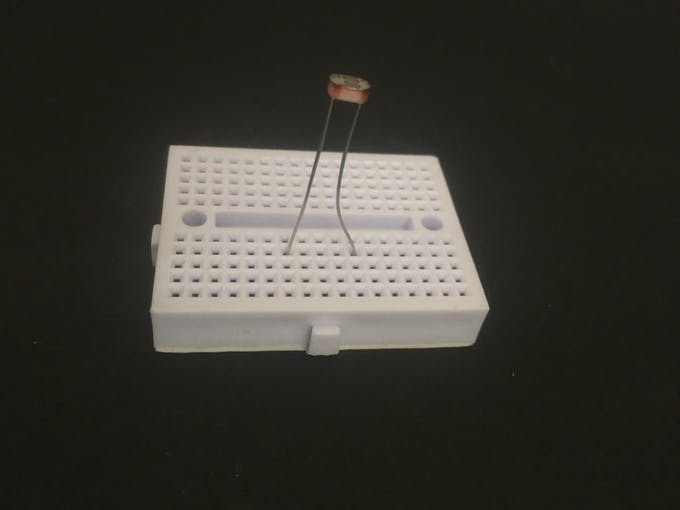
Step 3: Place the bolt WiFi module next to it
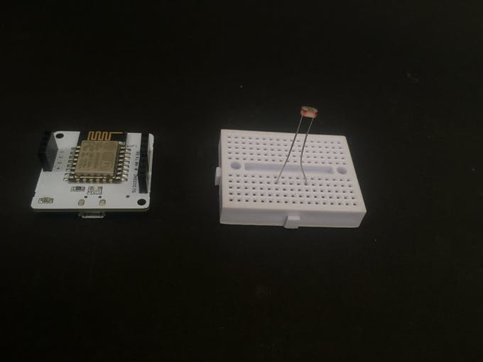
Step 4: Connecting one end of LDR to 5V of Bolt
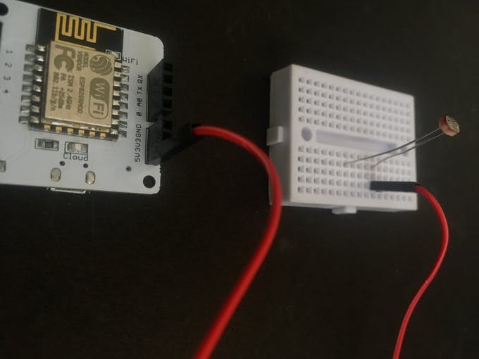
Step 5: Connecting the other end of LDR to A0 of Bolt
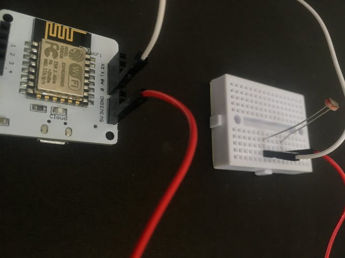
Step 7: Add the resistor in breadboard as shown
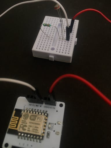
Step 8: Connecting resistor with the GND pin of Bolt WiFi Module
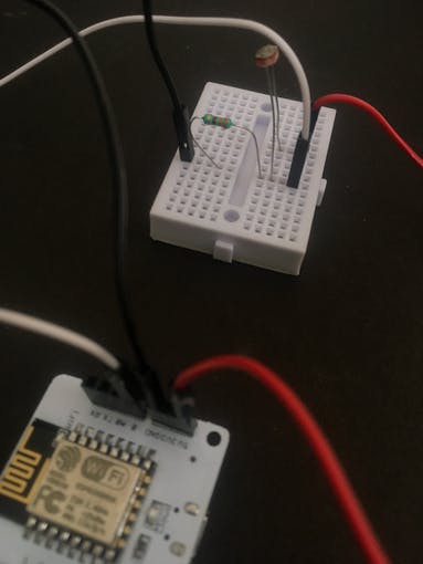
Check before you power on 👀
Make sure connections are made accurately. Ideally, review them again. Wrong connections can lead to a short circuit which can further lead to the device getting damaged permanently.
Step 9: Power on the Bolt device
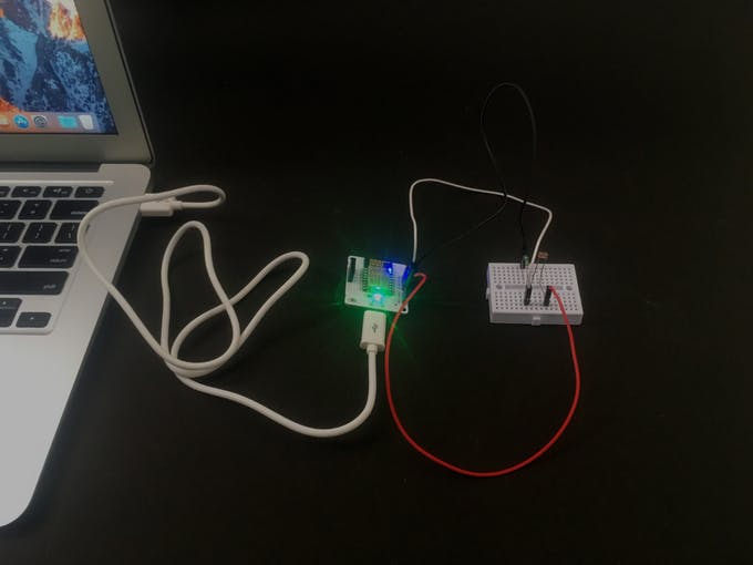
Now your circuit is ready. 🎉
In the next step, we will be to work on the software and cloud configuation.
Part B: Connect your Bolt device to the Bolt Cloud
Skip this step, if you already know how to connect your Bolt device to the Bolt Cloud. To check if it is connected to Cloud, have a look at the green coloured Cloud LED on the Bolt WiFi module. It should be glowing.
Follow the steps in this project to set up the device and to connect your Bolt device to the Bolt Cloud.:
Setting Up the Bolt WiFi Module
Yes. I am aware that we have repeated this step. But we realised that many users tend to miss out on this step so wanted to be double sure about it. Now that our Bolt is active, we are just a step away from completing the system. 😎
Part C: Collecting and visualising the data (Plotting Graph) on the Bolt Cloud
We will now work on the Bolt Cloud to build the software part of the system. Just follow these simple steps below:
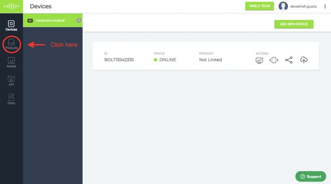
Step 1: Login into cloud.boltiot.com and click on the 'Product' tab.
Step 2:. Add a new product for your light monitoring system. Products are created once and can be used for multiple Bolt devices. This ensures scalability for the IoT products you build on Bolt.
Product names can only have alphabets, numbers, and underscore ( _ ) as a special character. Spaces are not allowed.
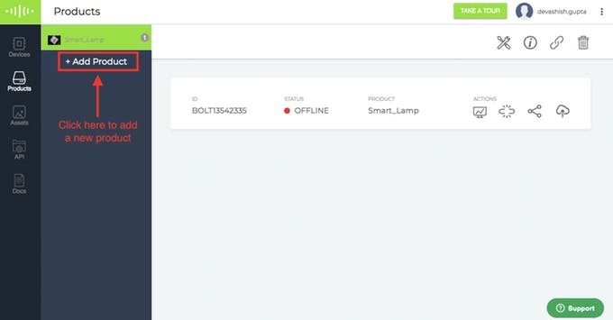
Step 3: We need to 'Configure your product'. For this click on the Configure Product icon as shown below in the image.
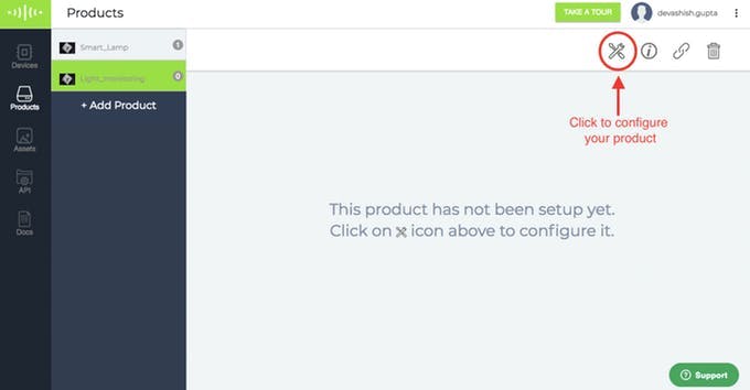
Select Configure tab
Step 4: Now choose the hardware pins which you plan to use for this project. Since LDR is an Analog Sensor and Bolt WiFi Module has only one Analogue pin, we have to choose only the A0 pin.
Step 5: Now give a suitable variable name to the pin value. By this, you will create a variable that will store the sensor value as it is received. We can then use this value in our project.
Step 6: With this, you have completed your hardware configuration. Save your configuration by clicking on the floppy disk icon.
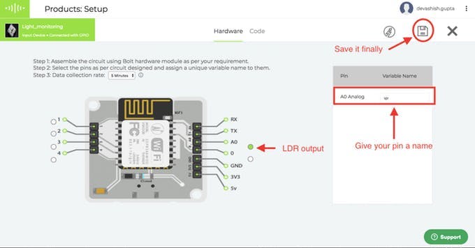
Hardware configuration
Step 7: Click on the 'Code' tab, and then click on the 'Import code' button to generate and import a new code.
While you can write your own code in HTML and Javascript for the Bolt cloud dashboard, in this tutorial of getting started, we shall import a template.
Here you will choose the option of Line Graph since we want to plot the line graph for our sensor value. However, in case you want to choose any other type of graph then you could do so.
The code tells the Bolt Cloud, how to plot the sensor data for visual representation.
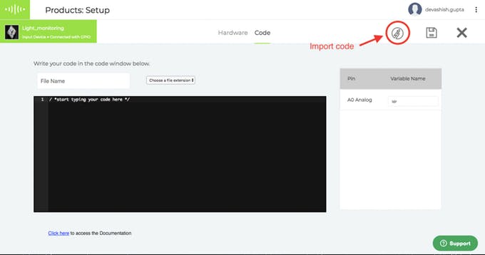
Understanding the code we imported
Now let me explain each line of the code so that you could make suitable changes as you wish.
setChartLibrary function sets the data visualisation library you would use. The most commonly used one on Bolt Cloud is the Google Library. However, you could use any other JavaScript or HTML code here to visualise the data.
setChartTitle function sets the title of the chart/graph. Give a suitable name for your graph here which will be shown in the heading of the page. This is different from the name of the code file.
setChartType function is where you choose which type of chart you want i.e. Line Graph, Bar Graph etc.
setAxisName will set the name for the X Axis and Y Axis
plotChart is where you choose which variable you want to choose in your chart.
If you want to know more about Data Visualisation and more features available in bolt cloud for it then you could click here. I would recomend that you visit this section after you have completed build this first project.
Step 8:
- Give a name to your code. Code names can only have an underscore ( _ ) as a special character. Spaces are not allowed.
- Choose the extension as js since this is a Javascript code.
- Save the configurations
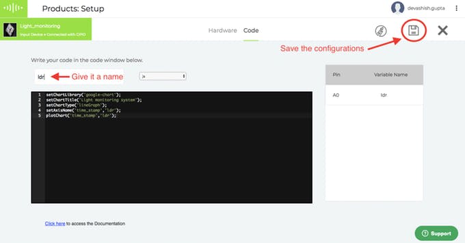
Give it a name
Step 9: Link Bolt with the 'Light_monitoring' product that you created. Linking allows your Bolt to access the configurations defined for a product.
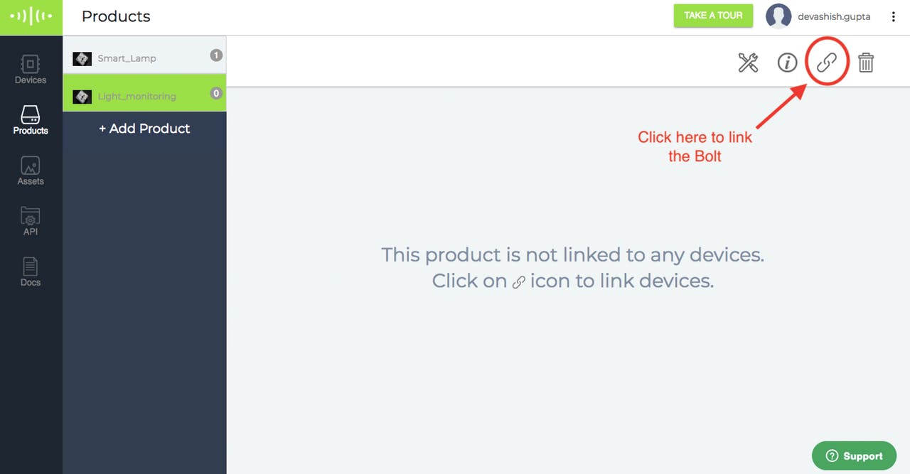
Link the Bolt
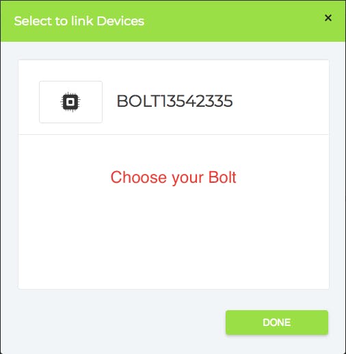
Choose your Bolt
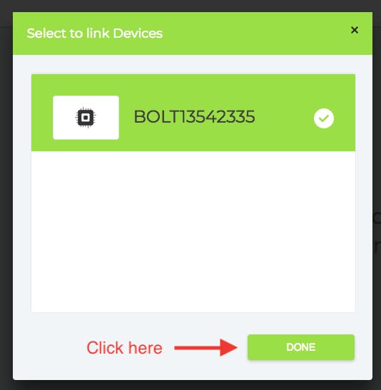
Save it
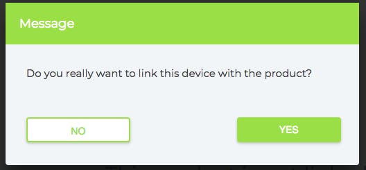
Click yes
Step 10: Deploy the code to your Bolt. Deploying means transferring the instructions and configuration to the Bolt device.
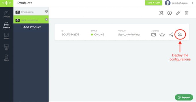
Deploy code
Step 11: We are now all set to see the output of our system. Click on the view this device button as shown with a red circle in the image below.
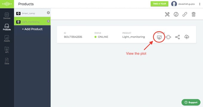
See output
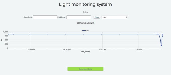
Step 12: The data is sent to the cloud once every 5 minutes (this time could be different based on the time you choose in configuration). If you get a few sample data points at a faster rate, click on the Push Data to Cloud button. This button will send the latest data value to Bolt Cloud.
Output Plot
Working principle
This project is based on the principle that whenever the light falling on the sensor changes, the resistance of sensor changes which is then converted into a change in voltage. The ADC pin on Bolt WiFi Module converted this analog voltage level into digital values which are shown on the graphs.
We connect the LDR between 5v pin and the analog input pin (A0), so that when light intensity increases, the resistance of LDR decreases so the voltage across the LDR decreases and as a result, the voltage on the analog input pin increases.
This means that as the light intensity increases, the voltage on the analog input pin also increases. The Bolt then converts that the voltage a 10 bit (10 places in binary number system) digital value that varies from 0-1024 (0 to 2 raised to 10).
This digital data is then sent to the cloud where it is plotted for visual representation.
Updated over 3 years ago
Now that you have learned to connect sensors to the Bolt Cloud, the next step is to try interfacing an output device
or you may connect the LM35 temperature sensor
